
Page 648 - Mechanical Engineers' Handbook (Volume 2)
P. 648
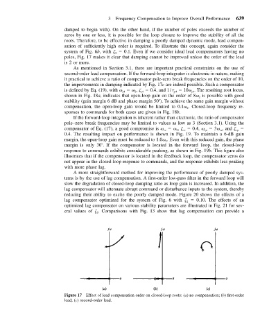
3 Frequency Compensation to Improve Overall Performance  639

                           damped to begin with). On the other hand, if the number of poles exceeds the number of
                           zeros by one or less, it is possible for the loop closure to improve the stability of all the
                           roots. Therefore, to be effective in damping a poorly damped dynamic mode, lead compen-
                           sation of sufficiently high order is required. To illustrate this concept, again consider the
                           system of Fig. 6b, with     0.1. Even if we consider ideal lead compensators having no
                                               2
                           poles, Fig. 17 makes it clear that damping cannot be improved unless the order of the lead
                           is 2 or more.
                              As mentioned in Section 3.1, there are important practical constraints on the use of
                           second-order lead compensation. If the forward-loop integrator is electronic in nature, making
                           it practical to achieve a ratio of compensator pole-zero break frequencies on the order of 10,
                           the improvements in damping indicated by Fig. 17c are indeed possible. Such a compensator
                           is defined by Eq. (19), with       ,     0.4, and 1/  p4    10  . The resulting root locus,
                                                                              z4
                                                       2
                                                         z4
                                                  z4
                           shown in Fig. 18a, indicates that open-loop gain on the order of 8  is possible with good
                                                                                 2
                           stability (gain margin 6 dB and phase margin 50 ). To achieve the same gain margin without
                           compensation, the open-loop gain would be limited to 0.1  . Closed-loop frequency re-
                                                                            2
                           sponses to commands for both cases are given in Fig. 18b.
                              If the forward-loop integration is inherent rather than electronic, the ratio of compensator
                           pole–zero break frequencies may be limited to values as low as 3 (Section 3.1). Using the
                           compensator of Eq. (17), a good compromise is       ,     0.4,   cp    3  , and   cp
                                                                          cz
                                                                        2
                                                                   cz
                                                                                         cz
                           0.4. The resulting impact on performance is shown in Fig. 19. To maintain a 6-dB gain
                           margin, the open-loop gain must be reduced to 1.0  . Even with this reduced gain, the phase
                                                                   2
                           margin is only 30 . If the compensator is located in the forward 1oop, the closed-loop
                           response to commands exhibits considerable peaking, as shown in Fig. 19b. This figure also
                           illustrates that if the compensator is located in the feedback loop, the compensator zeros do
                           not appear in the closed-loop response to commands, and the response exhibits less peaking
                           with more phase lag.
                              A more straightforward method for improving the performance of poorly damped sys-
                           tems is by the use of lag compensation. A first-order low-pass filter in the forward loop will
                           slow the degradation of closed-loop damping ratio as loop gain is increased. In addition, the
                           lag compensator will attenuate abrupt command or disturbance inputs to the system, thereby
                           reducing their ability to excite the poorly damped mode. Figure 20 shows the effects of a
                           lag compensator optimized for the system of Fig. 6 with     0.10. The effects of an
                                                                            2
                           optimized lag compensator on various stability parameters are illustrated in Fig. 21 for sev-
                           eral values of   . Comparisons with Fig. 13 show that lag compensation can provide a
                                        2


                           Figure 17 Effect of lead compensation order on closed-loop roots: (a) no compensation; (b) first-order
                           lead; (c) second-order lead.