
Page 713 - Mechanical Engineers' Handbook (Volume 2)
P. 713
704 General-Purpose Control Devices
FN 10*(feedrate along the path)/(length of the path)
For example, if the desired feed rate is 900 mm/min and the length of the path is 180 mm,
the feed-rate number is 50 (ƒ 0050). The inverse-time coded feed rate is expressed by a
four-digit number ranging from 0001 to 9999. This range of feed-rate numbers corresponds
to a minimum interpolation time of 0.06 s and a maximum interpolation time of 10 min.
Spindle speeds are prefixed with the code ‘‘s’’ followed by a coded number denoting
the speed. A common code for spindle speed is the magic-three code. To illustrate the steps
in computing the magic-three code, let us convert a spindle speed of 2345 rpm to magic-
4
three. The first step is to write the spindle speed as 0.2345 10 . The next step is to round
4
the decimal number to two decimal places and write the spindle speed as 0.23 10 . The
magic-three code can now be derived as 723, where the first digit 7 is given by adding 3 to
the power of 10 (4 3), and the second two digits are the rounded decimal numbers (23).
3
Similarly, a spindle speed of 754 rpm can be written as 0.75 10 , and the magic-three
code is 675.
Manual programming of the machine tool requires the programmer to compute the
dimensions of the part from a fixed reference point, called the origin. Since the NC unit
controls the path of the tool center point, the programmer must take into account the di-
mensions of the machine tool before generating the program. For instance, a cylindrical
cutting tool in a milling operation will traverse the periphery of the part at a distance equal
to its radius. The programmer also takes into account the limits on acceleration and decel-
eration of the machine tool in generating a program. For example, the feed rate for straight-
line milling can be much higher than the feed rate for milling an inside corner of a part.
The tool must be slowed down as it approaches the corner to prevent overshoot. Formulas
and graphs are often provided to assist the programmer in the above calculations.
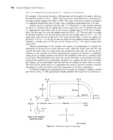
To illustrate manual part programming, let us consider an example of milling a simple
part shown in Fig. 15. The programmer initially identifies the origin for the Cartesian co-
Figure 15 Drawing of a part for machining.