Page 714 - Mechanical Engineers' Handbook (Volume 2)
P. 714
3 Numerical Controllers  705

                           ordinate system and a starting point for the tool. We will assume that the tool starts from
                           the origin (point PT.S). The programmer builds each block of the program, taking into
                           account the tool diameter and the dynamic constraints of the machine tool. Let us assume
                           that the milling tool in our example is cylindrical with a diameter of 12 mm.
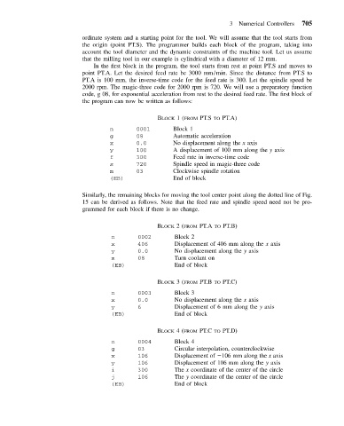
                              In the first block in the program, the tool starts from rest at point PT.S and moves to
                           point PT.A. Let the desired feed rate be 3000 mm/min. Since the distance from PT.S to
                           PT.A is 100 mm, the inverse-time code for the feed rate is 300. Let the spindle speed be
                           2000 rpm. The magic-three code for 2000 rpm is 720. We will use a preparatory function
                           code, g 08, for exponential acceleration from rest to the desired feed rate. The first block of
                           the program can now be written as follows:


                                                  BLOCK 1(FROM PT.S TO PT.A)
                                   n        0001       Block 1
                                   g        08         Automatic acceleration
                                   x        0.0        No displacement along the x axis
                                   y        100        A displacement of 100 mm along the y axis
                                   f        300        Feed rate in inverse-time code
                                   s        720        Spindle speed in magic-three code
                                   m        03         Clockwise spindle rotation
                                   (EB)                End of block


                           Similarly, the remaining blocks for moving the tool center point along the dotted line of Fig.
                           15 can be derived as follows. Note that the feed rate and spindle speed need not be pro-
                           grammed for each block if there is no change.


                                                  BLOCK 2(FROM PT.A TO PT.B)
                                    n       0002        Block 2
                                    x       406         Displacement of 406 mm along the x axis
                                    y       0.0         No displacement along the y axis
                                    m       08          Turn coolant on
                                    (EB)                End of block

                                                  BLOCK 3(FROM PT.B TO PT.C)
                                    n       0003        Block 3
                                    x       0.0         No displacement along the x axis
                                    y       6           Displacement of 6 mm along the y axis
                                    (EB)                End of block

                                                  BLOCK 4(FROM PT.C TO PT.D)
                                    n       0004        Block 4
                                    g       03          Circular interpolation, counterclockwise
                                    x       106         Displacement of  106 mm along the x axis
                                    y       106         Displacement of 106 mm along the y axis
                                    i       300         The x coordinate of the center of the circle
                                    j       106         The y coordinate of the center of the circle
                                    (EB)                End of block

