
Page 715 - Mechanical Engineers' Handbook (Volume 2)
P. 715
706 General-Purpose Control Devices
BLOCK 5(FROM PT.D TO PT.E)
n 0005 Block 5
x 206 Displacement of 206 mm along the x axis
y 0.0 No displacement along the y axis
(EB) End of block
BLOCK 6(FROM PT.E TO PT.F)
n 0006 Block 6
g 09 Automatic deceleration
x 0.0 No displacement along the x axis
y 112 Displacement of 112 mm along the y axis
m 30 Turn off spindle and coolant
(EB) End of block
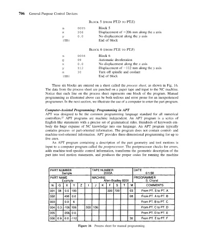
These six blocks are entered on a sheet called the process sheet, as shown in Fig. 16.
The data from the process sheet are punched on a paper tape and input to the NC machine.
Notice that each line on the process sheet represents one block of the program. Manual
programming as illustrated above can be both tedious and error prone for an inexperienced
programmer. In the next section, we illustrate the use of a computer to enter the part program.
Computer-Assisted Programming: Programming in APT
APT was designed to be the common programming language standard for all numerical
controllers. 25 APT programs are machine independent. An APT program is a series of
English-like statements with a precise set of grammatical rules. Hundreds of keywords em-
body the huge expanse of NC knowledge into one language. An APT program typically
contains process- or part-oriented information. The program does not contain control- and
machine-tool-oriented information. APT provides three-dimensional programming for up to
five axes.
An APT program containing a description of the part geometry and tool motions is
input to a computer program called the postprocessor. The postprocessor checks for errors,
adds machine-tool-specific control information, transforms the geometric description of the
part into tool motion statements, and produces the proper codes for running the machine
Figure 16 Process sheet for manual programming.