Page 718 - Mechanical Engineers' Handbook (Volume 2)
P. 718
3 Numerical Controllers  709

                           tool must remain to the right of the line LIN1 as seen from the tool in the direction of
                           motion between PT1 and PT2. This move statement is written as follows:
                              TLRGT, GORGT/LIN1, PAST, LIN2
                           The next step is to move the tool from PT2 to PT3 along the circle CIRC1:

                              TLRGT, GOLFT/CIRC1, PAST, LIN3
                           The next two motion statements to complete the motion around the part are as follows:
                              GOFWD/LIN3, PAST, LIN4
                              TLRGT, GOLFT/LIN4, PAST, LIN1
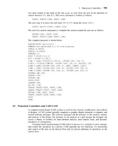
                           The complete program is shown below:

                           PARTNO A345, Revision 2
                           REMARK Part machined in 3/4 inch Aluminum
                           INTOL/0.00005
                           OUTTOL/0.00005
                           CUTTER/12
                           STPT   POINT/0,0,0
                           PT1   POINT/0,106,0
                           LIN1   LINE/(POINT/0,106,0), (POINT/400, 106, 0)
                           CIRC1   CIRCLE/CENTER, (POINT/300, 106, 0), RADIUS, 100
                           LIN2   LINE/(POINT/400, 206, 0), LEFT, TANTO, CIRC1
                           LIN3   LINE/(POINT/400, 206, 0), (POINT/100, 206, 0)
                           LIN4   LINE/(POINT/100, 206, 0), (POINT/100, 106, 0)
                           SPINDL/ON, CLW
                           FEDRAT/300
                           COOLNT/ON
                           FROM/STPT
                           INDIRP/PT1
                           GO/TO, LIN1
                           TLRGT, GORGT/LIN1, PAST, LIN2
                           TLRGT, GOLFT/CIRC1, PAST, LIN3
                           GOFWD/LIN3, PAST, LIN4
                           TLRGT, GOLFT/LIN4, PAST, LIN1
                           STOP
                           FINI


            3.5  Numerical Controllers and CAD/CAM
                           A computer-aided design (CAD) system is used for the creation, modification, and analysis
                           of designs. A CAD system typically comprises a graphics display terminal, a computer, and
                           several software packages. The software packages aid the designer in the creation, editing,
                           and analysis of the design. For instance, in the analysis of a part design, the designer can
                           access a library of routines for finite-element analysis, heat transfer study, and dynamic
                           simulation of mechanisms.
                              Computer-aided manufacturing (CAM) refers to the use of a computer to plan, manage,
                           and control the operations in a factory. CAM typically has two functions: (1) monitoring
                           and control of the data on the factory floor and (2) process planning of operations on the
                           factory floor.

