
Page 722 - Mechanical Engineers' Handbook (Volume 2)
P. 722
4 Robot Controllers 713
Main CPU unit
Compact PCI bus
Main CPU board
Optional
Personal computer
Human board
interface
Teach pendant
Sensor
I/O Motion Ethernet
Control Control
Etc.
Servoamplifier Manipulator
I/O unit
Servoamplifier Auxiliary axis
Operation Field bus
Option:
panel interface
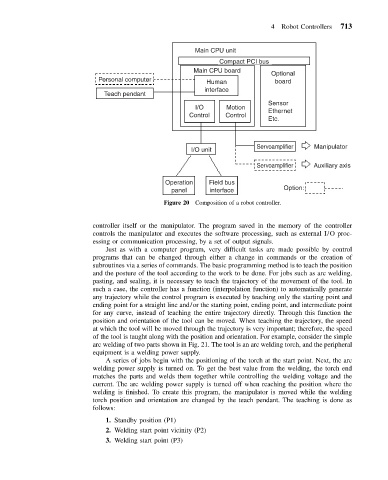
Figure 20 Composition of a robot controller.
controller itself or the manipulator. The program saved in the memory of the controller
controls the manipulator and executes the software processing, such as external I/O proc-
essing or communication processing, by a set of output signals.
Just as with a computer program, very difficult tasks are made possible by control
programs that can be changed through either a change in commands or the creation of
subroutines via a series of commands. The basic programming method is to teach the position
and the posture of the tool according to the work to be done. For jobs such as arc welding,
pasting, and sealing, it is necessary to teach the trajectory of the movement of the tool. In
such a case, the controller has a function (interpolation function) to automatically generate
any trajectory while the control program is executed by teaching only the starting point and
ending point for a straight line and/or the starting point, ending point, and intermediate point
for any curve, instead of teaching the entire trajectory directly. Through this function the
position and orientation of the tool can be moved. When teaching the trajectory, the speed
at which the tool will be moved through the trajectory is very important; therefore, the speed
of the tool is taught along with the position and orientation. For example, consider the simple
arc welding of two parts shown in Fig. 21. The tool is an arc welding torch, and the peripheral
equipment is a welding power supply.
A series of jobs begin with the positioning of the torch at the start point. Next, the arc
welding power supply is turned on. To get the best value from the welding, the torch end
matches the parts and welds them together while controlling the welding voltage and the
current. The arc welding power supply is turned off when reaching the position where the
welding is finished. To create this program, the manipulator is moved while the welding
torch position and orientation are changed by the teach pendant. The teaching is done as
follows:
1. Standby position (P1)
2. Welding start point vicinity (P2)
3. Welding start point (P3)