
Page 102 - Mechanical Engineers' Handbook (Volume 4)
P. 102
13 Flow Measurements 91
Other methods of measuring fluid velocities include length–time measurements with
floats or neutral-buoyancy particles, rotating instruments such as anemometers and current
meters, hot-wire and hot-film anemometers, and laser-doppler anemometers.
13.3 Volumetric and Mass Flow Fluid Measurements
Liquid flow rates in pipes are commonly measured with commercial water meters; with
rotameters; and with venturi, nozzle, and orifice meters. These latter types provide an ob-
struction in the flow and make use of the resulting pressure change to indicate the flow rate.
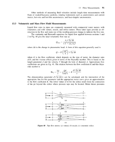
The continuity and Bernoulli equations for liquid flow applied between sections 1 and
2 in Fig. 40 give the ideal volumetric flow rate as
A 2g
h
2
Q ideal
1 (A /A ) 2
2
1
where
h is the change in piezometric head. A form of this equation generally used is
Q K
2
d
4 2g
h
where K is the flow coefficient, which depends on the type of meter, the diameter ratio
d/D, and the viscous effects given in terms of the Reynolds number. This is based on the
length parameter d and the velocity V through the hole of diameter d. Approximate flow
coefficients are given in Fig. 41. The relation between the flow coefficient K and this Reyn-
olds number is
Vd Qd d 2g
h
Re K
d
2
v 1 ⁄4 d v v
The dimensionless parameter d 2g
h/v can be calculated, and the intersection of the
appropriate line for this parameter and the appropriate meter curve gives an approximation
to the flow coefficient K. The lower values of K for the orifice result from the contraction
of the jet beyond the orifice where pressure taps may be located. Meter throat pressures
Figure 40 Pipe flow meters: (a) venturi; (b) nozzle; (c) concentric orifice.