
Page 97 - Mechanical Engineers' Handbook (Volume 4)
P. 97
86 Fluid Mechanics
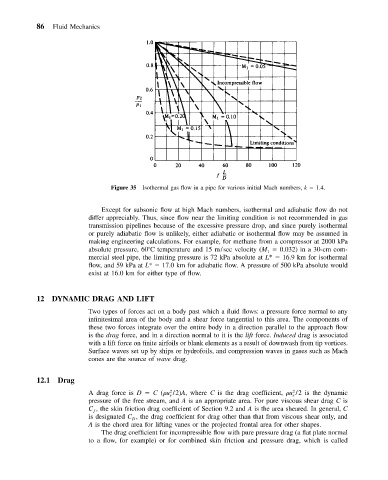
Figure 35 Isothermal gas flow in a pipe for various initial Mach numbers, k 1.4.
Except for subsonic flow at high Mach numbers, isothermal and adiabatic flow do not
differ appreciably. Thus, since flow near the limiting condition is not recommended in gas
transmission pipelines because of the excessive pressure drop, and since purely isothermal
or purely adiabatic flow is unlikely, either adiabatic or isothermal flow may be assumed in
making engineering calculations. For example, for methane from a compressor at 2000 kPa
absolute pressure, 60 C temperature and 15 m/sec velocity (M 0.032) in a 30-cm com-
1
mercial steel pipe, the limiting pressure is 72 kPa absolute at L* 16.9 km for isothermal
flow, and 59 kPa at L* 17.0 km for adiabatic flow. A pressure of 500 kPa absolute would
exist at 16.0 km for either type of flow.
12 DYNAMIC DRAG AND LIFT
Two types of forces act on a body past which a fluid flows: a pressure force normal to any
infinitesimal area of the body and a shear force tangential to this area. The components of
these two forces integrate over the entire body in a direction parallel to the approach flow
is the drag force, and in a direction normal to it is the lift force. Induced drag is associated
with a lift force on finite airfoils or blank elements as a result of downwash from tip vortices.
Surface waves set up by ships or hydrofoils, and compression waves in gases such as Mach
cones are the source of wave drag.
12.1 Drag
A drag force is D C ( u /2)A, where C is the drag coefficient, u /2 is the dynamic
2
2
s
s
pressure of the free stream, and A is an appropriate area. For pure viscous shear drag C is
C , the skin friction drag coefficient of Section 9.2 and A is the area sheared. In general, C
ƒ
is designated C , the drag coefficient for drag other than that from viscous shear only, and
D
A is the chord area for lifting vanes or the projected frontal area for other shapes.
The drag coefficient for incompressible flow with pure pressure drag (a flat plate normal
to a flow, for example) or for combined skin friction and pressure drag, which is called