
Page 94 - Mechanical Engineers' Handbook (Volume 4)
P. 94
11 Viscous Fluid Flow in Ducts 83
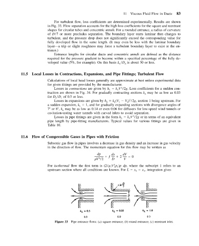
For turbulent flow, loss coefficients are determined experimentally. Results are shown
in Fig. 33. Flow separation accounts for the high loss coefficients for the square and reentrant
shapes for circular tubes and concentric annuli. For a rounded entrance, a radius of curvature
of D/7 or more precludes separation. The boundary layer starts laminar then changes to
turbulent, and the pressure drop does not significantly exceed the corresponding value for
fully developed flow in the same length. (It may even be less with the laminar boundary
layer—a trip or slight roughness may force a turbulent boundary layer to exist at the en-
trance.)
Entrance lengths for circular ducts and concentric annuli are defined as the distance
required for the pressure gradient to become within a specified percentage of the fully de-
veloped value (5%, for example). On this basis L /D is about 30 or less.
e
h
11.5 Local Losses in Contractions, Expansions, and Pipe Fittings; Turbulent Flow
Calculations of local head losses generally are approximate at best unless experimental data
for given fittings are provided by the manufacturer.
2
Losses in contractions are given by h k V /2g. Loss coefficients for a sudden con-
L
L
traction are shown in Fig. 34. For gradually contracting sections k may be as low as 0.03
L
for D /D of 0.5 or less.
1
2
2
Losses in expansions are given by h k (V V ) /2g, section 1 being upstream. For
L
L
2
1
a sudden expansion, k 1, and for gradually expanding sections with divergence angles of
L
7 or 8 , k may be as low as 0.14 or even 0.06 for diffusers for low-speed wind tunnels or
L
cavitation-testing water tunnels with curved inlets to avoid separation.
Losses in pipe fittings are given in the form h k V /2g or in terms of an equivalent
2
L
L
pipe length by pipe-fitting manufacturers. Typical values for various fittings are given in
Table 10.
11.6 Flow of Compressible Gases in Pipes with Friction
Subsonic gas flow in pipes involves a decrease in gas density and an increase in gas velocity
in the direction of flow. The momentum equation for this flow may be written as
dp dx dV
ƒ 2 0
2
V /2 D V
2
For isothermal flow the first term is (2/ Vp )p dp, where the subscript 1 refers to an
1 1 1
upstream section where all conditions are known. For L x x , integration gives
2 1
Figure 33 Pipe entrance flows: (a) square entrance; (b) round entrance; (c) reentrant inlet.