Page 256 - Mechanical Engineers' Handbook (Volume 4)
P. 256

8 Heat Transfer  245

                                 Radial heat flow path           r x       r y
                                 r                              1         2
                                 X   tD/r  2                    2.25      0.5625
                                 R   k/H r                      0.4       0.2
                                  ln Y /(X   0.1) from Fig. 23  1.3       1.7
                                      c
                                   /Y from Fig. 24              0.41      0.26
                                 Y s  c
                                                                0.0611    0.455
                                 Y c
                                                                0.025     0.119
                                 Y s
                              Combined factors:

                                                                           T   T c
                                                                            g
                                                Y   0.0611   0.455   0.0278
                                                 c
                                                                           T   70
                                                                            g
                                                                         T   T
                                                Y   0.025   0.119   0.003    g  s
                                                 s
                                                                         T   70
                                                                          g
                              For T   2250 F,  T   2316 F
                                   c           g
                                                  2309 F
                                              T s
                                                           2300 F.
                           This is close enough to the desired T s
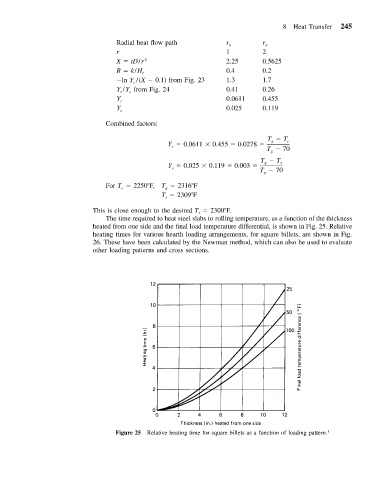
                              The time required to heat steel slabs to rolling temperature, as a function of the thickness
                           heated from one side and the final load temperature differential, is shown in Fig. 25. Relative
                           heating times for various hearth loading arrangements, for square billets, are shown in Fig.
                           26. These have been calculated by the Newman method, which can also be used to evaluate
                           other loading patterns and cross sections.


                                 Figure 25 Relative heating time for square billets as a function of loading pattern. 1
   251   252   253   254   255   256   257   258   259   260   261