
Page 261 - Mechanical Engineers' Handbook (Volume 4)
P. 261
250 Furnaces
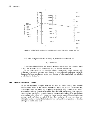
Figure 28 Convection coefficient (H c ) for forced convection inside tubes to air or flue gas. 1
With F the configuration factor from Fig. 30, heat-transfer coefficients are
0.6
H FkRe /D
c
Convection coefficients from this formula are approximately valid for 10 rows of tubes
or more, but are progressively reduced to a factor of 0.65 for a single row.
For gas to gas convection in a cross-flow tubular heat exchanger, overall resistance will
be the sum of factors for gas to the outer diameter of tubes, tube wall conduction, and inside
diameter of tubes to gas. Factors for the outer diameter of tubes may include gas radiation
as calculated in Section 7.5.
8.15 Fluidized-Bed Heat Transfer
For gas flowing upward through a particular bed, there is a critical velocity when pressure
drop equals the weight of bed material per unit area. Above that velocity, bed material will
be suspended in the gas stream in a turbulent flow condition. With the total surface area of
suspended particles on the order of a million times the inside surface area of the container,
convection heat transfer from gas to bed material is correspondingly large. Heat transfer from
suspended particles to load is by conduction during repeated impact. The combination can
provide overall coefficients upward of 10 times those available with open convection, per-
mitting the heating of thick and thin load sections to nearly uniform temperatures by allowing
a low gas to load thermal head.