
Page 264 - Mechanical Engineers' Handbook (Volume 4)
P. 264
9 Fluid Flow 253
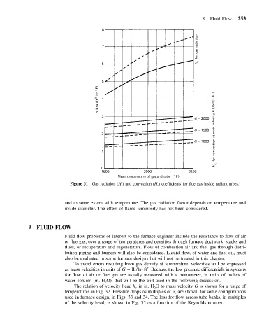
Figure 31 Gas radiation (H r ) and convection (H c ) coefficients for flue gas inside radiant tubes. 1
and to some extent with temperature. The gas radiation factor depends on temperature and
inside diameter. The effect of flame luminosity has not been considered.
9 FLUID FLOW
Fluid flow problems of interest to the furnace engineer include the resistance to flow of air
or flue gas, over a range of temperatures and densities through furnace ductwork, stacks and
flues, or recuperators and regenerators. Flow of combustion air and fuel gas through distri-
bution piping and burners will also be considered. Liquid flow, of water and fuel oil, must
also be evaluated in some furnace designs but will not be treated in this chapter.
To avoid errors resulting from gas density at temperature, velocities will be expressed
as mass velocities in units of G lb/hr ft . Because the low pressure differentials in systems
2
for flow of air or flue gas are usually measured with a manometer, in units of inches of
water column (in. H O), that will be the unit used in the following discussion.
2
The relation of velocity head h v in in. H O to mass velocity G is shown for a range of
2
temperatures in Fig. 32. Pressure drops as multiples of h v are shown, for some configurations
used in furnace design, in Figs. 33 and 34. The loss for flow across tube banks, in multiples
of the velocity head, is shown in Fig. 35 as a function of the Reynolds number.