
Page 266 - Mechanical Engineers' Handbook (Volume 4)
P. 266
9 Fluid Flow 255
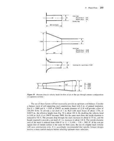
Figure 33 Pressure drop in velocity heads for flow of air or flue gas through entrance configurations
or expansion sections. 1
The use of these factors will not necessarily provide an optimum cost balance. Consider
a furnace stack of self-supporting steel construction, lined with 6 in. of gunned insulation.
For G 2000 and h v 0.05 at 1500 F, an inside diameter of 12 ft will provide a flow of
226,195 lb/hr. To provide a net draft of 1 in. H O with stack losses of about 1.75h v or
2
0.0875 in., the effective height from Fig. 38 is about 102 ft. By doubling the velocity head
to 0.10 in. H O, G at 1500 F becomes 3000. For the same mass flow, the inside diameter is
2
reduced to 9.8 ft. The pressure drop through the stack increases to about 0.175 in., and the
height required to provide a net draft of 1 in. increases to about 110 ft. The outside diameter
2
2
area of the stack is reduced from 4166 ft to 11 3.1416 110 3801 ft . If the cost per
square foot of outside surface is the same for both cases, the use of a higher stack velocity
will save construction costs. It is accordingly recommended that specific furnace designs
receive a more careful analysis before selecting optimum mass velocities.