
Page 262 - Mechanical Engineers' Handbook (Volume 4)
P. 262
8 Heat Transfer 251
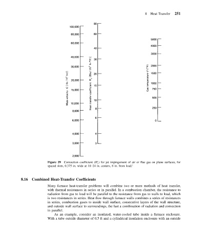
Figure 29 Convection coefficient (H c ) for jet impingement of air or flue gas on plane surfaces, for
spaced slots, 0.375 in. wide at 18–24 in. centers, 8 in. from load. 1
8.16 Combined Heat-Transfer Coefficients
Many furnace heat-transfer problems will combine two or more methods of heat transfer,
with thermal resistances in series or in parallel. In a combustion chamber, the resistance to
radiation from gas to load will be parallel to the resistance from gas to walls to load, which
is two resistances in series. Heat flow through furnace walls combines a series of resistances
in series, combustion gases to inside wall surface, consecutive layers of the wall structure,
and outside wall surface to surroundings, the last a combination of radiation and convection
in parallel.
As an example, consider an insulated, water-cooled tube inside a furnace enclosure.
With a tube outside diameter of 0.5 ft and a cylindrical insulation enclosure with an outside