
Page 257 - Mechanical Engineers' Handbook (Volume 4)
P. 257
246 Furnaces
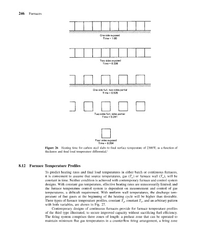
Figure 26 Heating time for carbon steel slabs to final surface temperature of 2300 F, as a function of
thickness and final load temperature differential. 1
8.12 Furnace Temperature Profiles
To predict heating rates and final load temperatures in either batch or continuous furnaces,
it is convenient to assume that source temperatures, gas (T ) or furnace wall (T ), will be
g
w
constant in time. Neither condition is achieved with contemporary furnace and control system
designs. With constant gas temperature, effective heating rates are unnecessarily limited, and
the furnace temperature control system is dependent on measurement and control of gas
temperatures, a difficult requirement. With uniform wall temperatures, the discharge tem-
perature of flue gases at the beginning of the heating cycle will be higher than desirable.
Three types of furnace temperature profiles, constant T , constant T , and an arbitrary pattern
g
w
with both variables, are shown in Fig. 27.
Contemporary designs of continuous furnaces provide for furnace temperature profiles
of the third type illustrated, to secure improved capacity without sacrificing fuel efficiency.
The firing system comprises three zones of length: a preheat zone that can be operated to
maintain minimum flue gas temperatures in a counterflow firing arrangement, a firing zone