
Page 279 - Mechanical Engineers' Handbook (Volume 4)
P. 279
268 Furnaces
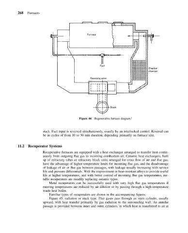
Figure 44 Regenerative furnace diagram. 1
stack. Fuel input is reversed simultaneously, usually by an interlocked control. Reversal can
be in cycles of from 10 to 30 min duration, depending primarily on furnace size.
11.2 Recuperator Systems
Recuperative furnaces are equipped with a heat exchanger arranged to transfer heat contin-
uously from outgoing flue gas to incoming combustion air. Ceramic heat exchangers, built
up of refractory tubes or refractory block units arranged for cross flow of air and flue gas,
have the advantage of higher temperature limits for incoming flue gas, and the disadvantage
of leakage of air or flue gas between passages, with leakage usually increasing with service
life and pressure differentials. With the improvement in heat-resistant alloys to provide useful
life at higher temperatures, and with better control of incoming flue gas temperatures, me-
tallic recuperators are steadily replacing ceramic types.
Metal recuperators can be successfully used with very high flue gas temperatures if
entering temperatures are reduced by air dilution or by passing through a high-temperature
waste-heat boiler.
Familiar types of recuperators are shown in the accompanying figures:
Figure 45: radiation or stack type. Flue gases pass through an open cylinder, usually
upward, with heat transfer primarily by gas radiation to the surrounding wall. An annular
passage is provided between inner and outer cylinders, in which heat is transferred to air at