
Page 281 - Mechanical Engineers' Handbook (Volume 4)
P. 281
270 Furnaces
1
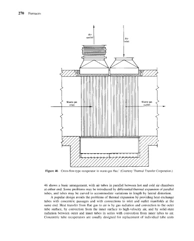
Figure 46 Cross-flow-type recuperator in waste-gas flue. (Courtesy Thermal Transfer Corporation.)
46 shows a basic arrangement, with air tubes in parallel between hot and cold air chambers
at either end. Some problems may be introduced by differential thermal expansion of parallel
tubes, and tubes may be curved to accommodate variations in length by lateral distortion.
A popular design avoids the problems of thermal expansion by providing heat-exchange
tubes with concentric passages and with connections to inlet and outlet manifolds at the
same end. Heat transfer from flue gas to air is by gas radiation and convection to the outer
tube surface, by convection from the inner surface to high-velocity air, and by solid-state
radiation between outer and inner tubes in series with convection from inner tubes to air.
Concentric tube recuperators are usually designed for replacement of individual tube units