
Page 319 - Mechanical Engineers' Handbook (Volume 4)
P. 319
308 Heat Exchangers, Vaporizers, Condensers
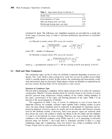
Table 2 Approximate Bypass Coefficient, C b
Bundle Type C b
Fixed tubesheet or U-tube 0.70
Split-ring floating head, seal strips 0.65
Pull-through floating head, seal strips 0.55
calculated by hand. The following very simplified equations are provided for a rough idea
of the range of pressure drop, in order to minimize preliminary specification of unrealistic
geometries.
(a) Tubeside (contains about 30% excess for nozzles)
P 0.025(L)(NP) 2(NP 1) 0.14
2
V
w
t
t
t (25)
D i g c f
where NP number of tubepasses.
(b) Shellside (contains about 30% excess for nozzles)
0.24(L)(D )( )(CV ) 2 0.14
P b s b s w (26)
s
gL P t ƒ
cbc
where g gravitational constant (4.17 10 for velocity in ft/hr and density in lb/ft ).
8
3
c
3.2 Shell and Tube Condensers
The condensing vapor can be on either the shellside or tubeside depending on process con-
straints. The ‘‘cold’’ fluid is often cooling tower water, but can also be another process fluid,
which is sensibly heated or boiled. In this section, the condensing-side heat-transfer coeffi-
cient and pressure drop are discussed. Single-phase coolants are handled, as explained in the
previous section. Boiling fluids will be discussed in a later section.
Selection of Condenser Type
The first task in designing a condenser, before rating can proceed, is to select the condenser
configuration. Mueller presents detailed charts for selection based on the criteria of system
14
pressure, pressure drop, temperature, fouling tendency of the coolant, fouling tendency of
the vapor, corrosiveness of the vapor, and freezing potential of the vapor. Table 3 is an
abstract of the recommendations of Mueller.
The suggestions in Table 3 may, of course, be ambiguous in case of more than one
important criterion, for example, corrosive vapor together with a fouling coolant. In these
cases, the most critical constraint must be respected, as determined by experience and en-
gineering judgment. Corrosive vapors are usually put on the tubeside, and chemical cleaning
used for the shellside coolant, if necessary. Since most process vapors are relatively clean
(not always the case!), the coolant is usually the dirtier of the two fluids and the tendency
is to put it on the tubeside for easier cleaning. Therefore, the most common shell and tube
condenser is the shellside condenser using TEMA types E, J, or X, depending on allowable
pressure drop; see Section 1. An F-type shell is sometimes specified if there is a large
condensing range and a temperature cross (see below), but, owing to problems with the
F-type, E-type units in series are often preferred in this case.