Page 315 - Mechanical Engineers' Handbook (Volume 4)
P. 315

304   Heat Exchangers, Vaporizers, Condensers

                             In a properly designed heat exchanger, it is unusual for F to be less than 0.7, and if
                          there is no temperature cross (T   t ), F will be 0.8 or greater. As a first approximation for
                                                  2
                                                      2
                          preliminary sizing and cost estimation, F may be taken as 0.85 for multitubepass exchangers
                          with temperature change of both streams and 1.0 for other cases.

           2.3 Overall Heat-Transfer Coefficient
                          The factor (U ) in Eq. (1) is the overall heat-transfer coefficient. It may be calculated by
                                     o
                          procedures described in Section 3, and is the reciprocal of the sum of all heat-transfer
                          resistances, as shown in the equation
                                               U   1/(R   R   R   R   R )                      (7)
                                                                 w
                                                o
                                                            ƒ o
                                                       h o
                                                                           ƒ i
                                                                      h i
                          where
                                                        R   1/h                                (8)
                                                         h o    o
                                                        R   (A /Ah )                           (9)
                                                         h i   o  i i
                                                             Ax
                                                        R     ow                              (10)
                                                         w
                                                             Ak
                                                              mw
                             Calculation of the heat-transfer coefficients h and h can be time consuming, since they
                                                                      i
                                                                o
                          depend on the fluid velocities, which, in turn, depend on the exchanger geometry. This is
                          usually done now by computer programs that guess correct exchanger size, calculate heat-
                          transfer coefficients, check size, adjust, and reiterate until satisfactory agreement between
                          guessed and calculated size is obtained. For first estimates by hand before size is known,
                          values of h and h , as well as values of the fouling resistances, R ƒ o  and R ƒ i , are recommended
                                  o
                                        i
                          by Bell for shell and tube heat exchangers. 10
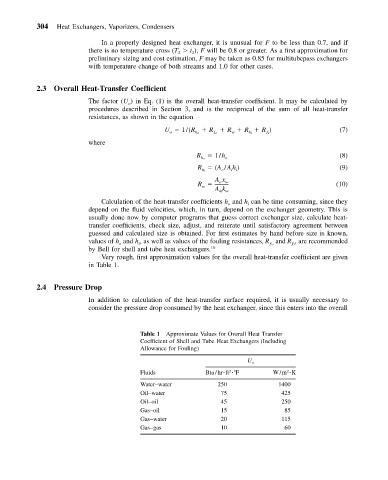
                             Very rough, first approximation values for the overall heat-transfer coefficient are given
                          in Table 1.
           2.4  Pressure Drop
                          In addition to calculation of the heat-transfer surface required, it is usually necessary to
                          consider the pressure drop consumed by the heat exchanger, since this enters into the overall


                                        Table 1 Approximate Values for Overall Heat Transfer
                                        Coefficient of Shell and Tube Heat Exchangers (Including
                                        Allowance for Fouling)

                                                                      U o
                                                                 2
                                                                                 2
                                        Fluids            Btu/hr ft   F      W/m  K
                                        Water–water          250              1400
                                        Oil–water             75               425
                                        Oil–oil               45               250
                                        Gas–oil               15                85
                                        Gas–water             20               115
                                        Gas–gas               10                60
   310   311   312   313   314   315   316   317   318   319   320