Page 314 - Mechanical Engineers' Handbook (Volume 4)
P. 314

2 Estimation of Size and Cost  303

                              (a) Sensible Heat Transfer
                                                       Q   WC (T   T )                          (2a)
                                                              p1
                                                                      1
                                                                 2
                                                            1
                                                           WC (t   t )                          (2b)
                                                            2
                                                              p21
                                                                     2
                              (b) Latent Heat Transfer
                                                           Q   W                                 (3)
                           where W   flow rate of boiling or condensing fluid
                                     latent heat of respective fluid
                           The mean temperature difference (MTD) and the overall heat transfer coefficient (U )inEq.
                                                                                            o
                           (1) are discussed in Sections 2.2 and 2.3, respectively. Once the required surface, or area,
                           (A ) is obtained, heat exchanger cost can be estimated. A comprehensive discussion on cost
                             o
                           estimation for several types of exchangers is given in Ref. 7. Cost charts for small- to
                           medium-sized shell and tube exchangers, developed in 1982, are given in Ref. 8.
            2.2  Mean Temperature Difference
                           The mean temperature difference (MTD) in Eq. (1) is given by the equation
                                                              F(T   T )
                                                       MTD       A   B                           (4)
                                                               ln(T /T )
                                                                  A
                                                                     B
                           where
                                                          T   T   t 2                            (5)
                                                               1
                                                           A
                                                          T   T   t 1                            (6)
                                                               2
                                                           B
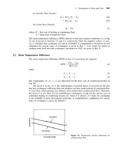
                           The temperatures (T , T , t , t ) are illustrated for the base case of countercurrent flow in
                                              2
                                           1
                                                   2
                                                1
                           Fig. 14.
                              The factor F in Eq. (4) is the multitubepass correction factor. It accounts for the fact
                           that heat exchangers with more than one tubepass can have some portions in concurrent flow
                           or cross flow, which produce less effective heat transfer than countercurrent flow. Therefore,
                           the factor F is less than 1.0 for multitubepass exchangers, except for the special case of
                           isothermal boiling or condensing streams for which F is always 1.0. Charts for calculating
                           F are available in most heat-transfer textbooks. A comprehensive compilation for various
                           types of exchangers is given by Taborek. 9


                                                                Figure 14 Temperature profiles illustrated for
                                                                countercurrent flow.
   309   310   311   312   313   314   315   316   317   318   319