
Page 309 - Mechanical Engineers' Handbook (Volume 4)
P. 309
298 Heat Exchangers, Vaporizers, Condensers
Figure 5 TEMA X-type shell. Figure 6 TEMA G-type shell.
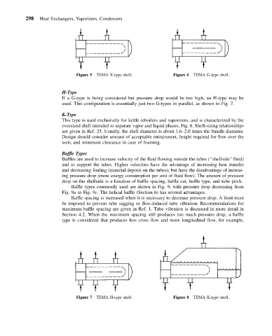
H-Type
If a G-type is being considered but pressure drop would be too high, an H-type may be
used. This configuration is essentially just two G-types in parallel, as shown in Fig. 7.
K-Type
This type is used exclusively for kettle reboilers and vaporizers, and is characterized by the
oversized shell intended to separate vapor and liquid phases, Fig. 8. Shell-sizing relationships
are given in Ref. 25. Usually, the shell diameter is about 1.6–2.0 times the bundle diameter.
Design should consider amount of acceptable entrainment, height required for flow over the
weir, and minimum clearance in case of foaming.
Baffle Types
Baffles are used to increase velocity of the fluid flowing outside the tubes (‘‘shellside’’ fluid)
and to support the tubes. Higher velocities have the advantage of increasing heat transfer
and decreasing fouling (material deposit on the tubes), but have the disadvantage of increas-
ing pressure drop (more energy consumption per unit of fluid flow). The amount of pressure
drop on the shellside is a function of baffle spacing, baffle cut, baffle type, and tube pitch.
Baffle types commonly used are shown in Fig. 9, with pressure drop decreasing from
Fig. 9a to Fig. 9c. The helical baffle (Section 6) has several advantages.
Baffle spacing is increased when it is necessary to decrease pressure drop. A limit must
be imposed to prevent tube sagging or flow-induced tube vibration. Recommendations for
maximum baffle spacing are given in Ref. 1. Tube vibration is discussed in more detail in
Section 4.2. When the maximum spacing still produces too much pressure drop, a baffle
type is considered that produces less cross flow and more longitudinal flow, for example,
Figure 7 TEMA H-type shell. Figure 8 TEMA K-type shell.