
Page 307 - Mechanical Engineers' Handbook (Volume 4)
P. 307
296 Heat Exchangers, Vaporizers, Condensers
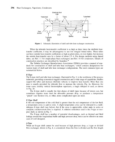
Figure 1 Schematic illustration of shell and tube heat exchanger construction.
When the tubeside heat-transfer coefficient is as high as three times the shellside heat-
transfer coefficient, it may be advantageous to use low integral finned tubes. These tubes
can have outside heat-transfer coefficients as high as plain tubes, or even higher, but increase
the outside heat-transfer area by a factor of about 2.5–4. For design methods using finned
tubes, see Ref. 11 for single-phase heat exchangers and Ref. 14 for condensers. Details of
construction practices are described by Saunders. 58
The Tubular Exchanger Manufacturers Association (TEMA) provides a manual of stan-
1
dards for construction of shell and tube heat exchangers, which contains designations for
various types of shell and tube heat exchanger configurations. The most common types are
summarized below.
E-Type
The E-type shell and tube heat exchanger, illustrated in Fig. 2, is the workhorse of the process
industries, providing economical rugged construction and a wide range of capabilities. Baffles
support the tubes and increase shellside velocity to improve heat transfer. More than one
pass is usually provided for tubeside flow to increase the velocity, Fig. 2a. However, for
some cases, notably vertical thermosiphon vaporizers, a single tubepass is used, as shown
in Fig. 2b.
The E-type shell is usually the first choice of shell types because of lowest cost, but
sometimes requires more than the allowable pressure drop, or produces a temperature
‘‘pinch’’ (see Section 4.4), so other, more complicated types are used.
F-Type Shell
If the exit temperature of the cold fluid is greater than the exit temperature of the hot fluid,
a temperature cross is said to exist. A slight temperature cross can be tolerated in a multi-
tubepass E-type shell (see below), but if the cross is appreciable, either units in series or
complete countercurrent flow is required. A solution sometimes used is the F-type or two-
pass shell, as shown in Fig. 3.
The F-type shell has a number of potential disadvantages, such as thermal and fluid
leakage around the longitudinal baffle and high pressure drop, but it can be effective in some
cases if well designed.
J-Type
When an E-type shell cannot be used because of high pressure drop, a J-type or divided
flow exchanger, shown in Fig. 4, is considered. Since the flow is divided and the flow length