
Page 320 - Mechanical Engineers' Handbook (Volume 4)
P. 320
3 Rating Methods 309
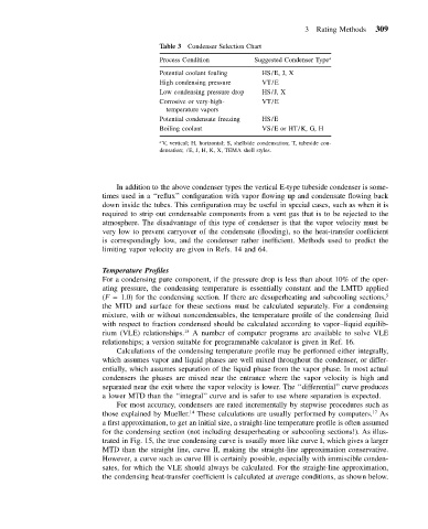
Table 3 Condenser Selection Chart
Process Condition Suggested Condenser Type a
Potential coolant fouling HS/E, J, X
High condensing pressure VT/E
Low condensing pressure drop HS/J, X
Corrosive or very-high- VT/E
temperature vapors
Potential condensate freezing HS/E
Boiling coolant VS/E or HT/K, G, H
a V, vertical; H, horizontal; S, shellside condensation; T, tubeside con-
densation; /E, J, H, K, X, TEMA shell styles.
In addition to the above condenser types the vertical E-type tubeside condenser is some-
times used in a ‘‘reflux’’ configuration with vapor flowing up and condensate flowing back
down inside the tubes. This configuration may be useful in special cases, such as when it is
required to strip out condensable components from a vent gas that is to be rejected to the
atmosphere. The disadvantage of this type of condenser is that the vapor velocity must be
very low to prevent carryover of the condensate (flooding), so the heat-transfer coefficient
is correspondingly low, and the condenser rather inefficient. Methods used to predict the
limiting vapor velocity are given in Refs. 14 and 64.
Temperature Profiles
For a condensing pure component, if the pressure drop is less than about 10% of the oper-
ating pressure, the condensing temperature is essentially constant and the LMTD applied
(F 1.0) for the condensing section. If there are desuperheating and subcooling sections, 5
the MTD and surface for these sections must be calculated separately. For a condensing
mixture, with or without noncondensables, the temperature profile of the condensing fluid
with respect to fraction condensed should be calculated according to vapor–liquid equilib-
rium (VLE) relationships. 15 A number of computer programs are available to solve VLE
relationships; a version suitable for programmable calculator is given in Ref. 16.
Calculations of the condensing temperature profile may be performed either integrally,
which assumes vapor and liquid phases are well mixed throughout the condenser, or differ-
entially, which assumes separation of the liquid phase from the vapor phase. In most actual
condensers the phases are mixed near the entrance where the vapor velocity is high and
separated near the exit where the vapor velocity is lower. The ‘‘differential’’ curve produces
a lower MTD than the ‘‘integral’’ curve and is safer to use where separation is expected.
For most accuracy, condensers are rated incrementally by stepwise procedures such as
17
those explained by Mueller. 14 These calculations are usually performed by computers. As
a first approximation, to get an initial size, a straight-line temperature profile is often assumed
for the condensing section (not including desuperheating or subcooling sections!). As illus-
trated in Fig. 15, the true condensing curve is usually more like curve I, which gives a larger
MTD than the straight line, curve II, making the straight-line approximation conservative.
However, a curve such as curve III is certainly possible, especially with immiscible conden-
sates, for which the VLE should always be calculated. For the straight-line approximation,
the condensing heat-transfer coefficient is calculated at average conditions, as shown below.