Page 417 - Mechanical Engineers' Handbook (Volume 4)
P. 417

406   Cooling Electronic Equipment

                          Singular Fans. There will be occasions when a singular fin, one whose tip comes to a point,
                          will be used as the most remote fin in an array. In this case the [ ] and [ ] matrices do not
                          exist and the fin is characterized by its input admittance. 38–40  Such a fin is the longitudinal
                          fin of triangular profile where
                                                          q   2hI (2mb)
                                                     Y     b     1                           (100)
                                                      in
                                                            b  mI (2mb)
                                                                 0
                          where
                                                        m        1/2
                                                              2h
                                                             k  b                            (101)

           3.2  The Cold Plate

                          The cold-plate heat exchanger or forced cooled electronic chassis is used to provide a ‘‘cold
                          wall’’ to which individual components and, for that matter, entire packages of equipment
                          may be mounted. Its design and performance evaluation follows a certain detailed procedure
                          that depends on the type of heat loading and whether the heat loading is on one or two sides
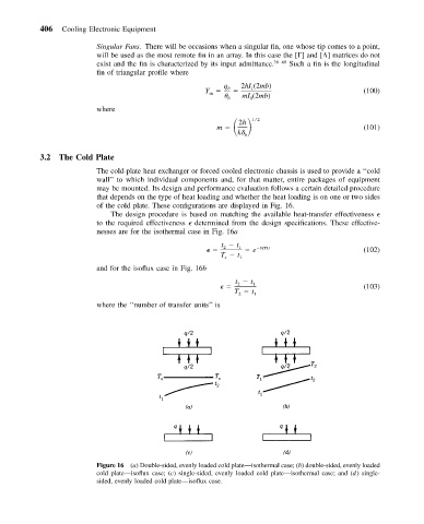
                          of the cold plate. These configurations are displayed in Fig. 16.
                             The design procedure is based on matching the available heat-transfer effectiveness
                          to the required effectiveness   determined from the design specifications. These effective-
                          nesses are for the isothermal case in Fig. 16a
                                                         t   t
                                                           2  1    e  NTU                    (102)
                                                         T   t 1
                                                          s
                          and for the isoflux case in Fig. 16b
                                                             t   t
                                                              2  1                           (103)
                                                             T   t
                                                              2   1
                          where the ‘‘number of transfer units’’ is


                          Figure 16 (a) Double-sided, evenly loaded cold plate—isothermal case; (b) double-sided, evenly loaded
                          cold plate—isoflux case; (c) single-sided, evenly loaded cold plate—isothermal case; and (d) single-
                          sided, evenly loaded cold plate—isoflux case.
   412   413   414   415   416   417   418   419   420   421   422