
Page 501 - Mechanical Engineers' Handbook (Volume 4)
P. 501
490 Cryogenic Systems
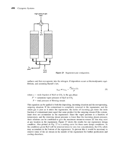
Figure 23 Regenerator pair configuration.
surfaces and then reevaporate into the nitrogen. If deposition occurs at thermodynamic equi-
librium, and assuming Raoult’s law,
P
2
y or y HO or CO 2 (9)
HO CO 2
P
2
where y mole fraction ofHOorCO inthe gas phase
2
2
P saturation vapor pressure ofHOorCO 2
2
P total pressure of flowing stream
This equation can be applied to both the depositing, incoming situation and the reevaporating,
outgoing situation. If the contaminant is completely removed in the regenerator, and the
return gas is pure as it enters the regenerator, the moles of incoming gas times the mole
fraction of contaminant must equal that same product for the outgoing stream if the contam-
inant does not accumulate in the regenerator. Since the vapor pressure is a function of
temperature, and the returning stream pressure is lower than the incoming stream pressure,
these relations can be combined to give the maximum stream-to-stream T that may exist
at any location in the regenerator. Figure 27 shows the results for one regenerator design
condition. Also plotted on Fig. 27 is a cooling curve for these same design conditions. At
the conditions given H O will be removed down to very low concentrations, but CO solids
2
2
may accumulate in the bottom of the regenerator. To prevent this it would be necessary to
remove some of the air stream in the middle of the regenerator for further purification and
cooling elsewhere.