Page 499 - Mechanical Engineers' Handbook (Volume 4)
P. 499

488   Cryogenic Systems

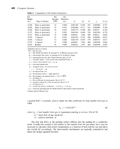
                          Table 4 Computation of Fin Surface Geometrics a
                          Fin                    Fin      Fin
                          Height                Spacing  Thickness
                          (in.)  Type of Surface  (FPI)   (in.)    A  c    A  ht  B    r h   A r /A ht
                          0.200  Plain or perforated  14  0.008  0.001185  0.596  437  0.001986  0.751
                          0.200  Plain or perforated  14  0.012  0.001086  0.577  415  0.001884  0.760
                          0.250  Plain or perforated  10  0.025  0.001172  0.500  288  0.00234  0.750
                          0.375  Plain or perforated  8  0.025   0.001944  0.600  230  0.003240  0.778
                          0.375  Plain or perforated  15  0.008  0.00224  1.064  409  0.00211  0.862
                          0.250  1 ⁄8 lanced      15     0.012   0.001355  0.732  420  0.001855  0.813
                          0.250  1 ⁄8 lanced      14     0.020   0.001150  0.655  378  0.001751  0.817
                          0.375  1 ⁄8 lanced      15     0.008   0.00224  1.064  409  0.002108  0.862
                          0.455  Ruffled           16     0.005   0.002811  1.437  465  0.001956  0.893
                          a Definition and use of terms:
                          FPI   fins per inch
                                              2
                           A    free stream area factor, ft /passage/in. of effective passage width
                            c
                                               2
                           A    heat-transfer area factor, ft /passage/in./ft of effective length
                            ht
                                                              2
                            B   heat-transfer area per unit volume between plates, ft /ft 3
                           r   hydraulic radius   cross section area/wetted perimeter, ft
                            h
                           A   effective heat-transfer area   A    0
                            r                     ht
                           A   total heat-transfer area
                            ht
                               weighted surface effectiveness factor
                            0
                               1   (A /A )(1     ) f
                                   r  ht
                           A   fin heat-transfer area
                            f
                               fin efficiency factor   [tanh (mL)]/ml
                            f
                           ml   fin geometry and material factor   (b/s)  2h/k
                            b   fin height, ft
                                                         2
                            h   film coefficient for heat transfer, Btu/hr ft   F
                            k   thermal conductivity of the fin material, Btu/hr ft  F
                            s   fin thickness, ft
                           U   overal heat transfer coefficient   1/(A/hA   A/hA )
                                                         a
                                                        a
                                                                b
                                                              b
                           a,b   subscripts indicating the two fluids between which heat is being transferred
                          Courtesy Stewart-Warner Corp.
                          a packed bed 28  is normally used to obtain the film coefficient for heat transfer from gas to
                          solid:
                                                      h   1.31(G/d) 0,93                       (8)
                                                       gs
                                                                                      2
                          where h   heat transfer from gas to regenerator packing or reverse, J/hr m  K
                                gs
                                G   mass flow of gas, kg/hr m 2
                                d   particle diameter, m
                             The heat that flows to the packing surface diffuses into the packing by a conductive
                          mode. Usually this transfer is fast relative to the transfer from the gas phase, but it may be
                          necessary to calculate solid surface temperatures as a function of heat-transfer rate and adjust
                          the overall  T accordingly. The heat-transfer mechanisms are typically symmetrical and
                          hence the design equation becomes
   494   495   496   497   498   499   500   501   502   503   504