
Page 503 - Mechanical Engineers' Handbook (Volume 4)
P. 503
492 Cryogenic Systems
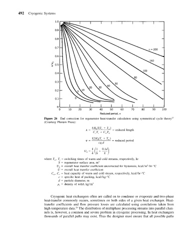
Figure 26 End correction for regenerator heat-transfer calculation using symmetrical cycle theory 27
(Courtesy Plenum Press):
4HS(T T )
0 c w reduced length
c
c
CT CT w
w
12H (T T )
0 c w reduced period
c d
s
U
1 1
0.1d
0
4 h k
where T w , T c switching times of warm and cold streams, respectively, hr
S regenerator surface area, m 2
2
U 0 overall heat transfer coefficient uncorrected for hysteresis, kcal/m hr C
U overall heat transfer coefficient
C w , C c heat capacity of warm and cold stream, respectively, kcal/hr C
c specific heat of packing, kcal/kg C
d particle diameter, m
s density of solid, kg/m 3
Cryogenic heat exchangers often are called on to condense or evaporate and two-phase
heat-transfer commonly occurs, sometimes on both sides of a given heat exchanger. Heat-
transfer coefficients and flow pressure losses are calculated using correlations taken from
high-temperature data. The distribution of multiphase processing streams into parallel chan-
29
nels is, however, a common and severe problem in cryogenic processing. In heat exchangers
thousands of parallel paths may exist. Thus the designer must ensure that all possible paths