
Page 500 - Mechanical Engineers' Handbook (Volume 4)
P. 500
3 Cryogenic Heat-Transfer Methods 489
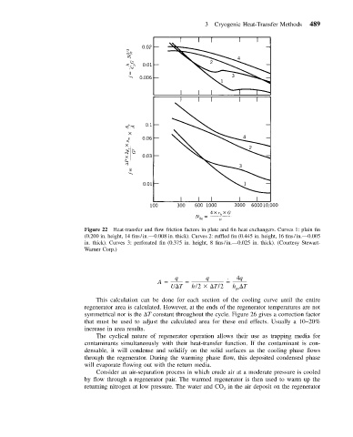
Figure 22 Heat-transfer and flow friction factors in plate and fin heat exchangers. Curves 1: plain fin
(0.200 in. height, 14 fins/in.—0.008 in. thick). Curves 2: ruffled fin (0.445 in. height, 16 fins/in.—0.005
in. thick). Curves 3: perforated fin (0.375 in. height, 8 fins/in.—0.025 in. thick). (Courtesy Stewart-
Warner Corp.)
q q 4q
˙
A
U T h/2 T/2 h T
gs
This calculation can be done for each section of the cooling curve until the entire
regenerator area is calculated. However, at the ends of the regenerator temperatures are not
symmetrical nor is the T constant throughout the cycle. Figure 26 gives a correction factor
that must be used to adjust the calculated area for these end effects. Usually a 10–20%
increase in area results.
The cyclical nature of regenerator operation allows their use as trapping media for
contaminants simultaneously with their heat-transfer function. If the contaminant is con-
densable, it will condense and solidify on the solid surfaces as the cooling phase flows
through the regenerator. During the warming phase flow, this deposited condensed phase
will evaporate flowing out with the return media.
Consider an air-separation process in which crude air at a moderate pressure is cooled
by flow through a regenerator pair. The warmed regenerator is then used to warm up the
returning nitrogen at low pressure. The water and CO in the air deposit on the regenerator
2