
Page 495 - Mechanical Engineers' Handbook (Volume 4)
P. 495
484 Cryogenic Systems
Compact heat-exchanger designs of many sorts have been used, but only the most common
types will be discussed here.
3.1 Coiled-Tube-in-Shell Exchangers
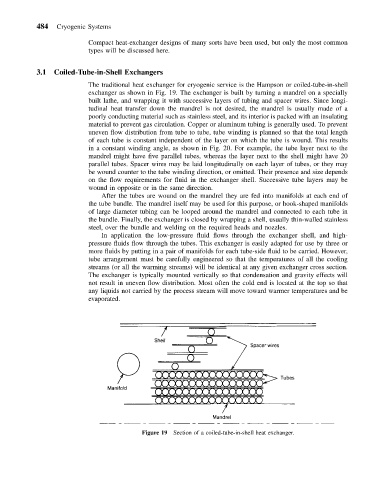
The traditional heat exchanger for cryogenic service is the Hampson or coiled-tube-in-shell
exchanger as shown in Fig. 19. The exchanger is built by turning a mandrel on a specially
built lathe, and wrapping it with successive layers of tubing and spacer wires. Since longi-
tudinal heat transfer down the mandrel is not desired, the mandrel is usually made of a
poorly conducting material such as stainless steel, and its interior is packed with an insulating
material to prevent gas circulation. Copper or aluminum tubing is generally used. To prevent
uneven flow distribution from tube to tube, tube winding is planned so that the total length
of each tube is constant independent of the layer on which the tube is wound. This results
in a constant winding angle, as shown in Fig. 20. For example, the tube layer next to the
mandrel might have five parallel tubes, whereas the layer next to the shell might have 20
parallel tubes. Spacer wires may be laid longitudinally on each layer of tubes, or they may
be wound counter to the tube winding direction, or omitted. Their presence and size depends
on the flow requirements for fluid in the exchanger shell. Successive tube layers may be
wound in opposite or in the same direction.
After the tubes are wound on the mandrel they are fed into manifolds at each end of
the tube bundle. The mandrel itself may be used for this purpose, or hook-shaped manifolds
of large diameter tubing can be looped around the mandrel and connected to each tube in
the bundle. Finally, the exchanger is closed by wrapping a shell, usually thin-walled stainless
steel, over the bundle and welding on the required heads and nozzles.
In application the low-pressure fluid flows through the exchanger shell, and high-
pressure fluids flow through the tubes. This exchanger is easily adapted for use by three or
more fluids by putting in a pair of manifolds for each tube-side fluid to be carried. However,
tube arrangement must be carefully engineered so that the temperatures of all the cooling
streams (or all the warming streams) will be identical at any given exchanger cross section.
The exchanger is typically mounted vertically so that condensation and gravity effects will
not result in uneven flow distribution. Most often the cold end is located at the top so that
any liquids not carried by the process stream will move toward warmer temperatures and be
evaporated.
Figure 19 Section of a coiled-tube-in-shell heat exchanger.