
Page 492 - Mechanical Engineers' Handbook (Volume 4)
P. 492
2 Cryogenic Refrigeration and Liquefaction Cycles 481
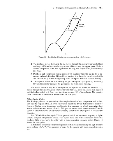
Figure 16 The idealized Stirling cycle represented on a T–S diagram.
2. The displacer moves down, and the gas moves through the annular water-cooled heat
exchanger (13) and the annular regenerator (14) reaching the upper space (5) in a
cooled, compressed state. The regenerator packing, fine copper wool, is warmed by
this flow.
3. Displacer and compressor pistons move down together. Thus the gas in (5) is ex-
panded and cooled further. This cold gas receives heat from the chamber walls (18)
and interior fins (15) thus refrigerating these solid parts and their external finning.
4. The displacer moves up, thus moving the gas from space (5) to space (4). In flowing
through the annular passages the gas recools the regenerator packing.
The device shown in Fig. 17 is arranged for air liquefaction. Room air enters at (23),
passes through the finned structure where water and then CO freeze out, and is then liquified
2
as it is further cooled as it flows over the finned surface (18) of the cylinder. The working
fluid, usually He, is supplied as needed from the tank (27).
Other Engine Cycles
The Stirling cycle can be operated as a heat engine instead of as a refrigerator and, in fact,
that was the original intent. In 1918 Vuilleumier patented a device that combines these two
forms of Stirling cycle to produce a refrigerator that operated on a high-temperature heat
source rather than on a source of work. This process has received recent attention 24 and is
useful in situations where a heat source is readily available but where power is inaccessible
or costly.
The Gifford–McMahon cycles 25 have proven useful for operations requiring a light-
weight, compact refrigeration source. Two cycles exist: one with a displacer piston that
produces little or no work; the other with a work-producing expander piston. Figure 18
shows the two cycles.
In both these cycles the compressor operates continuously maintaining the high-pressure
surge volume of P , T . The sequence of steps for the system with work-producing piston
1
1
are