
Page 487 - Mechanical Engineers' Handbook (Volume 4)
P. 487
476 Cryogenic Systems
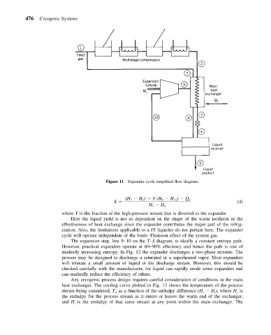
Figure 11 Expander cycle simplified flow diagram.
(H H ) Y (H H ) Q
X 7 2 9 10 L (4)
H H 5
7
where Y is the fraction of the high-pressure stream that is diverted to the expander.
Here the liquid yield is not so dependent on the shape of the warm isotherm or the
effectiveness of heat exchange since the expander contributes the major part of the refrig-
eration. Also, the limitations applicable to a JT liquefier do not pertain here. The expander
cycle will operate independent of the Joule–Thomson effect of the system gas.
The expansion step, line 9–10 on the T–S diagram, is ideally a constant entropy path.
However, practical expanders operate at 60–90% efficiency and hence the path is one of
modestly increasing entropy. In Fig. 12 the expander discharges a two-phase mixture. The
process may be designed to discharge a saturated or a superheated vapor. Most expanders
will tolerate a small amount of liquid in the discharge stream. However, this should be
checked carefully with the manufacturer, for liquid can rapidly erode some expanders and
can markedly reduce the efficiency of others.
Any cryogenic process design requires careful consideration of conditions in the main
heat exchanger. The cooling curve plotted in Fig. 13 shows the temperature of the process
stream being considered, T , as a function of the enthalpy difference (H H ), where H is
o
i
o
i
the enthalpy for the process stream as it enters or leaves the warm end of the exchanger,
and H is the enthalpy of that same stream at any point within the main exchanger. The
i