
Page 484 - Mechanical Engineers' Handbook (Volume 4)
P. 484
2 Cryogenic Refrigeration and Liquefaction Cycles 473
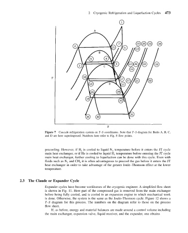
Figure 7 Cascade refrigeration system on T–S coordinates. Note that T–S diagram for fluids A, B, C,
and D are here superimposed. Numbers here refer to Fig. 8 flow points.
precooling. However, if H is cooled to liquid N temperature before it enters the JT cycle
2 2
main heat exchanger, or if He is cooled to liquid H temperature before entering the JT cycle
2
main heat exchanger, further cooling to liquefaction can be done with this cycle. Even with
fluids such as N and CH it is often advantageous to precool the gas before it enters the JT
2 4
heat exchanger in order to take advantage of the greater Joule–Thomson effect at the lower
temperature.
2.3 The Claude or Expander Cycle
Expander cycles have become workhorses of the cryogenic engineer. A simplified flow sheet
is shown in Fig. 11. Here part of the compressed gas is removed from the main exchanger
before being fully cooled, and is cooled in an expansion engine in which mechanical work
is done. Otherwise, the system is the same as the Joule–Thomson cycle. Figure 12 shows a
T–S diagram for this process. The numbers on the diagram refer to those on the process
flow sheet.
If, as before, energy and material balances are made around a control volume including
the main exchanger, expansion valve, liquid receiver, and the expander, one obtains