
Page 486 - Mechanical Engineers' Handbook (Volume 4)
P. 486
2 Cryogenic Refrigeration and Liquefaction Cycles 475
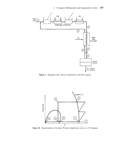
Figure 9 Simplified Joule–Thomson liquefaction cycle flow diagram.
Figure 10 Representation of the Joule–Thomson liquefaction cycle on a P–H diagram.