
Page 483 - Mechanical Engineers' Handbook (Volume 4)
P. 483
472 Cryogenic Systems
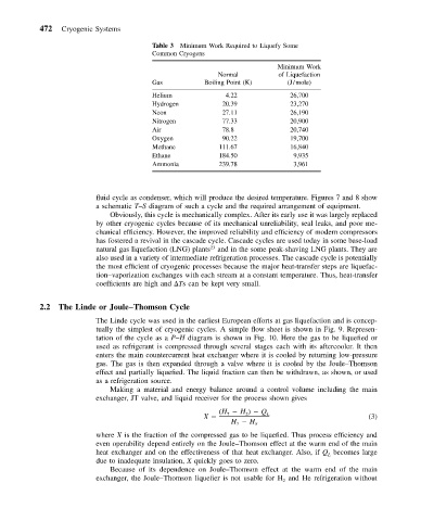
Table 3 Minimum Work Required to Liquefy Some
Common Cryogens
Minimum Work
Normal of Liquefaction
Gas Boiling Point (K) (J/mole)
Helium 4.22 26,700
Hydrogen 20.39 23,270
Neon 27.11 26,190
Nitrogen 77.33 20,900
Air 78.8 20,740
Oxygen 90.22 19,700
Methane 111.67 16,840
Ethane 184.50 9,935
Ammonia 239.78 3,961
fluid cycle as condenser, which will produce the desired temperature. Figures 7 and 8 show
a schematic T–S diagram of such a cycle and the required arrangement of equipment.
Obviously, this cycle is mechanically complex. After its early use it was largely replaced
by other cryogenic cycles because of its mechanical unreliability, seal leaks, and poor me-
chanical efficiency. However, the improved reliability and efficiency of modern compressors
has fostered a revival in the cascade cycle. Cascade cycles are used today in some base-load
23
natural gas liquefaction (LNG) plants and in the some peak-shaving LNG plants. They are
also used in a variety of intermediate refrigeration processes. The cascade cycle is potentially
the most efficient of cryogenic processes because the major heat-transfer steps are liquefac-
tion–vaporization exchanges with each stream at a constant temperature. Thus, heat-transfer
coefficients are high and Ts can be kept very small.
2.2 The Linde or Joule–Thomson Cycle
The Linde cycle was used in the earliest European efforts at gas liquefaction and is concep-
tually the simplest of cryogenic cycles. A simple flow sheet is shown in Fig. 9. Represen-
tation of the cycle as a P–H diagram is shown in Fig. 10. Here the gas to be liquefied or
used as refrigerant is compressed through several stages each with its aftercooler. It then
enters the main countercurrent heat exchanger where it is cooled by returning low-pressure
gas. The gas is then expanded through a valve where it is cooled by the Joule–Thomson
effect and partially liquefied. The liquid fraction can then be withdrawn, as shown, or used
as a refrigeration source.
Making a material and energy balance around a control volume including the main
exchanger, JT valve, and liquid receiver for the process shown gives
(H H ) Q
X 7 2 L (3)
H H 5
7
where X is the fraction of the compressed gas to be liquefied. Thus process efficiency and
even operability depend entirely on the Joule–Thomson effect at the warm end of the main
heat exchanger and on the effectiveness of that heat exchanger. Also, if Q becomes large
L
due to inadequate insulation, X quickly goes to zero.
Because of its dependence on Joule–Thomson effect at the warm end of the main
exchanger, the Joule–Thomson liquefier is not usable for H and He refrigeration without
2