
Page 488 - Mechanical Engineers' Handbook (Volume 4)
P. 488
2 Cryogenic Refrigeration and Liquefaction Cycles 477
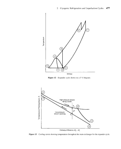
Figure 12 Expander cycle shown on a T–S diagram.
Figure 13 Cooling curves showing temperatures throughout the main exchanger for the expander cycle.