
Page 493 - Mechanical Engineers' Handbook (Volume 4)
P. 493
482 Cryogenic Systems
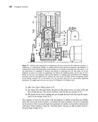
Figure 17 Stirling cycle arranged for air liquefaction reference points have the following meanings: 1,
compressor; 2, compression cylinder; 4, working fluid in space between compressor and displacer; 5,
working fluid in the cold head region of the machine; 6, two parallel connecting rods with cranks, 7, of
the main piston; 8, crankshaft; 9, displacer rod, linked to connecting rod, 10, and crank, 11, of the
displacer; 12, ports; 13, cooler; 14, regenerator; 15, freezer; 16, displacer piston, and 17, cap; 18, con-
denser for the air to be liquefied, with annular channel, 19, tapping pipe (gooseneck) 20, insulating
screening cover, 21, and mantel 22; 23, aperture for entry of air; 24, plates of the ice separator, joined
by the tubular structure, 25, to the freezer (15); 26, gas-tight shaft seal; 27, gas cylinder supplying
refrigerant; 28, supply pipe with one-way valve, 29. (Courtesy U.S. Philips Corp.)
1. Inlet valve opens filling system to P .
2
2. Gas enters the cold space below the piston as the piston moves up doing work and
thus cooling the gas. The piston continues, reducing the gas pressure to P .
1
3. The piston moves down pushing the gas through the heat load area and the regen-
erator to the storage vessel at P .
1
The sequence of steps for the system with the displacer is similar except that gas initially
enters the warm end of the cylinder, is cooled by the heat exchanger, and then is displaced
by the piston so that it moves through the regenerator for further cooling before entering the
cold space. Final cooling is done by ‘‘blowing down’’ this gas so that it enters the low-
pressure surge volume at P .
1