Page 494 - Mechanical Engineers' Handbook (Volume 4)
P. 494

3 Cryogenic Heat-Transfer Methods  483


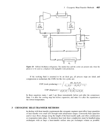
                           Figure 18 Gifford–McMahon refrigerator. The dashed line and the cooler are present only when the
                           piston is to be used as a displacer with negligible work production.


                              If the working fluid is assumed to be an ideal gas, all process steps are ideal, and
                           compression is isothermal, the COPs for the two cycles are:
                                       COP (work producing)   1       RT 1n P /P 1
                                                                             2
                                                                        1
                                                                                    ]
                                                                    T [1   (P /P )
                                                                 C P 03     4  3  (k 1) / k  1
                                                                    P   P
                                             COP (displacer)         3    1
                                                            P (T /T   P /P )1n P /P 1
                                                                       1
                                                                  3
                                                                          3
                                                                               2
                                                                1
                                                             3
                           In these equations states 1 and 2 are those immediately before and after the compressor.
                           State 3 is after the cooling step but before expansion, and state 4 is after the expansion at
                           the lowest temperature.
            3   CRYOGENIC HEAT-TRANSFER METHODS
                           In dealing with heat-transfer requirements the cryogenic engineer must effect large quantities
                           of heat transfer over small  Ts through wide temperature ranges. Commonly heat capacities
                           and/or mass flows change along the length of the heat-transfer path, and often condensation
                           or evaporation takes place. To minimize heat leak these complexities must be handled using
                           exchangers with as large a heat-transfer surface area per exchanger volume as possible.
   489   490   491   492   493   494   495   496   497   498   499