Page 490 - Mechanical Engineers' Handbook (Volume 4)
P. 490
2 Cryogenic Refrigeration and Liquefaction Cycles  479


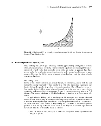
                           Figure 14 Calculation of W L in the main heat exchanger using Eq. (6) and showing the comparison
                           between JT and Claude cycles.


            2.4  Low-Temperature Engine Cycles
                           The possibility that Carnot cycle efficiency could be approached by a refrigeration cycle in
                           which all pressure change occurs by compression and expansion has encouraged the devel-
                           opment of several cycles that essentially occur within an engine. In general, these have
                           proven useful for small-scale cryogenic refrigeration under unusual conditions as in space
                           vehicles. However, the Stirling cycle, discussed below, has been used for industrial-scale
                           production situations.

                           The Stirling Cycle
                           In this cycle a noncondensable gas, usually helium, is compressed, cooled both by heat
                           transfer to cooling water and by heat transfer to a cold solid matrix in a regenerator (see
                           Section 3.3), and expanded to produce minimum temperature. The cold gas is warmed by
                           heat transfer to the fluid or space being refrigerated and to the now-warm matrix in the
                           regenerator and returned to the compressor. Figure 16 shows the process path on a T–S
                           diagram. The process efficiency of this idealized cycle is identical to a Carnot cycle effi-
                           ciency.
                              In application the Stirling cycle is usually operated in an engine where compression and
                           expansion both occur rapidly with compression being nearly adiabatic. Figure 17 shows such
                           a machine. The compressor piston (1) and a displacer piston (16 with cap 17) operate off
                           the same crankshaft. Their motion is displaced by 90 . The result is that the compressor
                           position is near the top or bottom of its cycle as the displacer is in most rapid vertical
                           movement. Thus the cycle can be traced as follows:
                              1. With the displacer near the top of its stroke the compressor moves up compressing
                                 the gas in space 4.

