
Page 63 - Singiresu S. Rao-Mechanical Vibrations in SI Units, Global Edition-Pearson (2017)
P. 63
60 Chapter 1 Fundamentals oF Vibration
1.7.4 In many practical applications, several linear springs are used in combination. These
Combination springs can be combined into a single equivalent spring as indicated below.
of springs
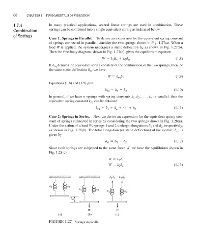
Case 1: Springs in Parallel. To derive an expression for the equivalent spring constant
of springs connected in parallel, consider the two springs shown in Fig. 1.27(a). When a
load W is applied, the system undergoes a static deflection d as shown in Fig. 1.27(b).
st
Then the free-body diagram, shown in Fig. 1.27(c), gives the equilibrium equation
W = k d + k d (1.8)
2 st
1 st
If k denotes the equivalent spring constant of the combination of the two springs, then for
eq
the same static deflection d , we have
st
W = k d (1.9)
eq st
Equations (1.8) and (1.9) give
k eq = k + k 2 (1.10)
1
In general, if we have n springs with spring constants k , k , c, k in parallel, then the
1
n
2
equivalent spring constant k can be obtained:
eq
k eq = k + k + g + k n (1.11)
2
1
Case 2: Springs in Series. Next we derive an expression for the equivalent spring con-
stant of springs connected in series by considering the two springs shown in Fig. 1.28(a).
Under the action of a load W, springs 1 and 2 undergo elongations d and d , respectively,
1
2
as shown in Fig. 1.28(b). The total elongation (or static deflection) of the system, d , is
st
given by
d = d + d 2 (1.12)
st
1
Since both springs are subjected to the same force W, we have the equilibrium shown in
Fig. 1.28(c):
W = k d
1 1
W = k d (1.13)
2 2
k d k d
1 st
2 st
k 1 k 2
k 1 k 2 k 1 k 2
d st
W W
(a) (b) (c)
FiGure 1.27 Springs in parallel.