
Page 111 - Mechanics Analysis Composite Materials
P. 111
96 Mechanics and analysis of composite materials
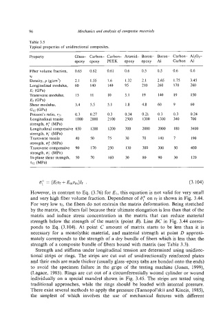
Table 3.5
Typical properties of unidirectional composites.
Property Glass- Carbon- Carbon- Aramid- Boron- Boron- Carbon- A1203-
epoxy epoxy PEEK epoxy epoxy A1 Carbon AI
Fiber volume fraction, 0.65 0.62 0.61 0.6 0.5 0.5 0.6 0.6
Vf
Density, p (g/cm3) 2.1 1.55 1.6 1.32 2.1 2.65 1.75 3.45
Longitudinal modulus, 60 140 140 95 210 260 170 260
El (GPa)
Transverse modulus, 13 11 IO 5.1 19 140 19 150
E2 @Pa)
Shear modulus, 3.4 5.5 5.1 1.8 4.8 60 9 60
GU (GPa)
Poisson's ratio, v21 0.3 0.27 0.3 0.34 0.21 0.3 0.3 0.24
Longitudinal tensile 1800 2000 2100 2500 1300 1300 340 700
strength, 8: (MPa)
Longitudinal compressive 650 1200 1200 300 2000 2000 180 3400
strength, a; (MPa)
Transverse tensile 40 50 75 30 70 I40 7 190
strength, (MPa)
Transverse compressive 90 170 250 130 300 300 50 400
strength, 8, (MPa)
In-plane shear strength, 50 70 160 30 80 90 30 120
712 WPa)
5; = (Ef~f+Emvm)Ef . (3.104)
However, in contrast to Eq. (3.76) for E,, this equation is not valid for very small
and very high fiber volume fraction. Dependence of if;' on uf is shown in Fig. 3.44.
For very low uf, the fibers do not restrain the matrix deformation. Being stretched
by the matrix, the fibers fail because their ultimate elongation is less than that of the
matrix and induce stress concentration in the matrix that can reduce material
strength below the strength of the matrix (point B). Line BC in Fig. 3.44 corres-
ponds to Eq. (3.104). At point C amount of matrix starts to be less than it is
necessary for a monolythic material, and material strength at point D approxi-
mately corresponds to the strength of a dry bundle of fibers which is less than the
strength of a composite bundle of fibers bound with matrix (see Table 3.3).
Strength and stiffness under longitudinal tension are determined using unidirec-
tional strips or rings. The strips are cut out of unidirectionally reinforced plates
and their ends are made thicker (usually glass+poxy tabs are bonded onto the ends)
to avoid the specimen failure in the grips of the testing machine (Jones, 1999),
(Lagace, 1985). Rings are cut out of a circumferentially wound cylinder or wound
individually on a special mandrel shown in Fig. 3.45. The strips are tested using
traditional approaches, while the rings should be loaded with internal pressure.
There exist several methods to apply the pressure (Tarnopol'skii and Kincis, 1985),
the simplest of which involves the use of mechanical fixtures with different