
Page 114 - Mechanics Analysis Composite Materials
P. 114
Chapter 3. Mechanics of a unidirectional ply 99
o,,MPa
2800
2000
,
1600 ,
1200 ,
800
0
0 0.5 1 1.5 2 2.5 3
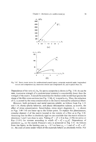
Fig. 3.42. Stress-strain curves for unidirectional aramidqoxy composite material under longitudinal
tension and compression (a), transverse tension and compression (b), and in-plane shear (b).
Dependence of the ratio i?;/@,,, for epoxy composite is shown in Fig. 3.50. As can be
seen, transverse strength of a unidirectional material is considerably lower than the
strength of the matrix. It should be noted that for the first-order model that ignores the
shape of the fiber cross-sections (see Fig. 3.34), 5; is equal to am.Thus, the reduction
of is caused by the stress concentration in the matrix induced by cylindrical fibers.
However, both polymeric and metal matrices exhibit, as follows from Fig. I. 11
and 1.14, elastic-plastic behavior, and plastic deformation reduces, as known, the
effect of stress concentration. Nevertheless, stress-strain diagrams if: - E, shown
in Figs. 3.40-3.43 are linear up to the failure point. To explain this phenomenon,
consider element A of the matrix located in the vicinity of a fiber as in Fig. 3.38.
Assuming that the fiber is absolutely rigid we can conclude that the matrix strains in
directions 1 and 3 are close to zero. Taking E;' = 8y = 0 in Eqs. (3.94) we arrive at
Eqs. (3.101) for stresses according to which of = oy = ,urnor.Dependence of
parameter ,urn on the matrix Poisson's ratio is presented in Fig. 3.51. As follows
from this figure, in the limiting case v, = 0.5 we have pm = 1 and a? = or = CT?,
i.e., the state of stress under which all the materials behave as absolutely brittle. For