
Page 122 - Mechanics Analysis Composite Materials
P. 122
Chapter 3. Mechanics of a unidirectional ply 107
t'f= 0.6, becomes as high as 25 for uf = 0.75. This means that $ dramatically
decreases for higher of, and the fracture mode shown in Fig. 3.57 becomes quite
typical for composites with high fiber volume fractions.
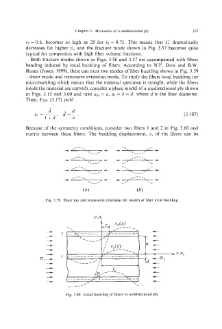
Both fracture modes shown in Figs. 3.56 and 3.57 are accompanied with fibers
bending induced by local buckling of fibers. According to N.F. Dow and B.W.
Rosen (Jones, 1999), there can exist two modes of fiber buckling shown in Fig. 3.59
- shear mode and transverse extension mode. To study the fibers local buckling (or
microbuckling which means that the material specimen is straight, while the fibers
inside the material are curved), consider a plane model of a unidirectional ply shown
in Figs. 3.15 and 3.60 and take a, = a, af= 6 = d, where d is the fiber diameter.
Then, Eqs. (3.17) yield
(3.107)
Because of the symmetry conditions, consider two fibers 1 and 2 in Fig. 3.60 and
matrix between these fibers. The buckling displacement, li, of the fibers can be
Fig. 3.59. Shear (a) and transverse extension (b) modes of fiber local buckling
1
--
3 I
, T-.
, ,
/
\-
Fig. 3.60. Local buckling of fibers in unidirecltional