
Page 178 - Mechanics Analysis Composite Materials
P. 178
Chapter 4. Mechanics of a composite layer 163
Q, ,MPa
E,,%
0 0.2 0.4 0.6 0.8 1 12 1.4 1.6 1.8
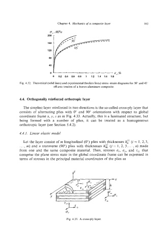
Fig. 4.32. Theoretical (solid lines) and experimental (broken lines) stress-strain diagrams for 30" and 45"
off-axis tension of a boron-aluminum composite.
4.4. Orthogonally reinforced orthotropic layer
The simplest layer reinforced in two directions is the so-called cross-ply layer that
consists of alternating plies with 0" and 90" orientations with respect to global
coordinate frame x, y, z as in Fig. 4.33. Actually, this is a laminated structure, but
being formed with a number of plies, it can be treated as a homogeneous
orthotropic layer (see Section 5.4.2).
4.4.1. Linear elastic model
Let the layer consist of m longitudinal (00)plies with thicknesses At) (i = 1, 2, 3,
ci)
. ..,rn) and n transverse (90") plies with thicknesses h,, (j= 1, 2, 3,. ..,n) made
from one and the same composite material. Then, stresses cy,and z.~~that
comprise the plane stress state in the global coordinate frame can be expressed in
terms of stresses in the principal material coordinates of the plies as
J
Y
Fig. 4.33. A cross-ply layer.