
Page 177 - Mechanics Analysis Composite Materials
P. 177
162 Mechanics and analysis of composite materials
As an example of application of a nonlinear elastic material model described by
Eqs. (4.60), consider a two-matrix fiberglass composite whose stress-strain curves in
the principal material coordinates are presented in Fig. 4.16. These curves allowed
us to determine coefficients 'b' and 'c' in Eqs. (4.60). To find coupling coefficients
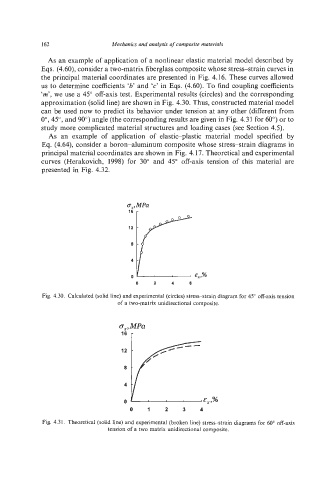
'm',we use a 45" off-axis test. Experimental results (circles) and the corresponding
approximation (solid line) are shown in Fig. 4.30. Thus, constructed material model
can be used now to predict its behavior under tension at any other (different from
0", 45", and 90")angle (the corresponding results are given in Fig. 4.31 for 60") or to
study more complicated material structures and loading cases (see Section 4.5).
As an example of application of elastic-plastic material model specified by
Eq. (4.64), consider a boron-aluminum composite whose stress-strain diagrams in
principal material coordinates are shown in Fig. 4.17. Theoretical and experimental
curves (Herakovich, 1998) for 30" and 45" off-axis tension of this material are
presented in Fig. 4.32.
a,,MPa
0 2 4 6
Fig. 4.30. Calculated (solid line) and experimental (circles) stress-strain diagram for 45" off-axis tension
of a two-matrix unidirectional composite.
E, ,%
0 1 2 3 4
Fig. 4.31. Theoretical (solid line) and experimental (broken line) stress-strain diagrams for 60" off-axis
tension of a two matrix unidirectional composite.