
Page 361 - Mechanics Analysis Composite Materials
P. 361
346 Mechanics and analysis of' cornposite materials
Now introduce an additional aluminum layer in the foam core as shown
in Fig. 7.37(b). As follows from Fig. 7.38(b) this layer suppresses tensile stress
in section a - a. Two intermediate aluminum layers (Fig. 7.37(c)) working as
generators of the compression stress waves eliminate the appearance of tensile stress
in this section. Naturally, the effect under discussion can be achieved for a limited
period of time. But actually, impact tensile stress is dangerous right after the pulse
action. Damping capacity of real structural materials (it was not taken into account
in the foregoing analysis) dramatically reduces the stress amplitude in time.
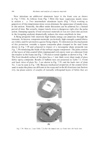
A flying projectile with relatively high kinetic energy can penetrate through the
laminate. As known, composite materials, particularly, high-strength aramid fabrics
are widely used for protection against flying objects. To demonstrate the mechanism
of this protection, consider a square composite plate clamped in the steel frame
shown in Fig. 7.39 and subjected to impact of a rectangular plane projectile (see
Fig. 7.39) simulating the blade of the turbojet engine compressor. The plate consists
of the layers of thin aramid fabric impregnated with epoxy resin at a distance from
the window in the frame (see Fig. 7.39) and co-cured together as shown in Fig. 7.40.
The front (loaded) surface of the plate has a 1 mm thick cover sheet made of glass
fabric-epoxy composite. Results of ballistic tests are presented in Table 7.2. Front
and back views of plate No. 2 are shown in Fig. 7.39, and the back view of plate
No. 3 can be seen in Fig. 7.40. Because mechanical properties of the aramid fabric
used to make the plates are different in the warp and in the fill directions (see Section
4.6), the plates consist of couples of mutually orthogonal layers of fabric that are
C
(b)
Fig. 7.39. Plate no. 2 (see Table 7.2) after the impact test: (a) front view; (b) back view