
Page 359 - Mechanics Analysis Composite Materials
P. 359
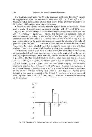
344                 Mechanics and analysis of composite materials

                For laminates, such as in Fig. 7.34, the boundary conditions, Eqs. (7.59) should
              be  supplemented with  the  interlaminar  conditions  uf) =   and  cy)= cry-’).
              Omitting rather  cumbersome solution that can be  found elsewhere (Vasiliev and
              Sibiryakov, 1985) present some numerical results.
                Consider the two-layered structure the first layer of which has thickness 15 mm
              and  is  made  of  aramid-epoxy  composite  material  with  El’) = 4.2  GPa,  pI =
              1.4 g/cm3and the second layer is made of boron-epoxy composite material and has
              E!2) = 4.55 GPa, p2 = 2g/cm3, h2  = 12mm. The duration of a rectangular pulse of
              external  pressure p  acting  on  the  surface  of  the  first  layer  is  tp = 5 x   s.
              Dependenceof the interlaminar (z = 15 mm) stress on time is shown in Fig. 7.36. As
              can be seen, at t M 3tp the tensile interface stress exceeds the intensity of the pulse of
              pressure by the factor of 1.27. This stress is a result of interaction of the direct stress
              wave  with  the  waves  reflected  from  the  laminate’s  inner,  outer,  and  interface
              surfaces. Thus, in a laminate, each interface surface generates elastic waves.
                For laminates consisting of more than two layers, the wave interaction becomes
              more complicated and, what is more important, can be controlled by  the proper
              stacking sequence of layers. As an example, consider a sandwich structure shown in
              Fig. 7.37(a).  The first  (loaded) layer  is  made  of  aluminum and  has  hl = 1 mm,
              E!’) = 72 GPa, pI = 2.7g/cm3, the second layer is a foam core with h2 = 10 mm,
              E!*) = 0.28 GPa,  pz = 0.25 g/cm3,  and  the  third  (load-carrying)  aramid+poxy
              composite layer has h3  = 12 mm, Ei3)= 10 GPa, p3 = l.4g/cm3. The duration of a
              rectangular pulse of external pressure is   s. Maximum tensile stress occurs in the
              middle plane of  the load-carrying layer (plane a - a in Fig. 7.37). Normal  stress
              induced in this plane is presented in Fig. 7.38(a). As can be seen, at the moment of
              time t equal to about 1.75 x  low5s this stress is tensile and can cause delamination
              of the structure.


                                   -
                                1.5

                                  1


                                0.5

                                  0
                                        4
                                -03

                                 -I

                                -1.5   -