
Page 354 - Mechanics Analysis Composite Materials
P. 354
Chapter 7. Environmental, special loading, and manufacturing efficts 339
4000 3I
logN
5
4
6
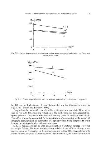
Fig. 7.28. Fatigue diagrams for a unidirectional carbon-epoxy composite loaded along the fibers with
various stress ratios.
3 4 5 6
Fig. 7.29. Tensile fatigue diagrams for a cross-ply (I) and fabric (2) carbon-epoxy composites.
be different for high stresses. Typical fatigue diagram for this case is shown in
Fig. 7.30 (Tamuzh and Protasov, 1986).
Fatigue has also some effect on the stiffness of composite materials. This can be
seen in Fig. 7.31 demonstrating reduction of the elastic modulus for a glass fabric-
epoxy-phenolic composite under low-cycle loading (Tamuzh and Protasov, 1986).
This effect should be accounted for in application of composites to the design of
structural members such as automobile leaf-springs which, being subjected to cyclic
loading, are designed under stiffness constraints.
Stiffness degradation can be used as an indication of material damage to predict
its fatigue failure. The most sensitive characteristic of the stiffness change is the
tangent modulus E, specified by the second equation in Eqs. (1 3).Dependence of E,
on the number of cycles, N,normalized to the number of cycles that cause material