
Page 353 - Mechanics Analysis Composite Materials
P. 353
338 Mechanics and analysis of composite materials
Here, N is the number of cycles to failure under stress OR, a and b are experimental
constants depending on frequency of cyclic loading, temperature and other
environmental factors, and on the stress ratio R = amitl/amax, where amax and amin
are the maximum and minimum stresses. It should be taken into account that results
of fatigue tests are characterized, as a rule with high scatter.
Factor R specifies the cycle type. The most common bending fatigue test provides
the symmetric cycle for which Omin = -a, amnx = a,and R = -1. Tensile load cycle
(amin= 0, omt,,= a) has R = 0, while compressive cycle (amin= -a, ami,,= 0) has
R + -00. Cyclic tension with a,,, > amin > 0 corresponds to 0 < R < 1, while
cyclic compression with 0 > a,,, > omin corresponds to 1 < R < 00. Fatigue
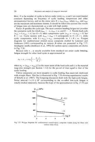
diagrams for unidirectional aramid-epoxy composite studied by Limonov and
Anderson (1991) corresponding to various R-values are presented in Fig. 7.27.
Analogous results (Anderson et al., 1991) for carbon-epoxy composites are shown
in Fig. 7.28.
Because only c-1 is usually available from standard test under cyclic bending,
fatigue strength for other load cycles is approximated as
where om= (amin+ omax)/2 is the mean stress of the load cycle and at is the material
long-term strength (see Section 7.3.2) for the period of time equal to that of the
cyclic loading.
Fabric composites are more sensitive to cyclic loading than materials reinforced
with straight fibers. This fact is illustrated in Fig. 7.29 showing experimental results
of Schulte et al. (1987). The foregoing discussion deals with the high-cycle fatigue.
Initial interval 1 <N < lo3 corresponding to the so-called low-cycle fatigue is
usually studied separately, because the slope of the approximation in Eq. (7.57) can
*0° t 0
3 4 5 6
Fig. 7.27. Fatigue diagrams for unidirectional aramid-epoxy composite loaded along the fibers with
various stress ratios.