
Page 366 - Mechanics Analysis Composite Materials
P. 366
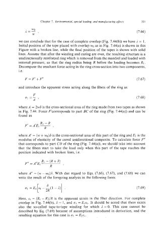
Chapter 7.  Environmental, special loading,and manufacfuring effects   35I

                                                                              (7.66)


            we can conclude that for the case of complete overlap (Fig. 7.44(b)) we have R  = 1.
            Initial position of the tape placed with overlap wo as in Fig. 7.44(a) is shown in this
            Figure with a broken line, while the final position of the tapes is shown with solid
            lines. Assume that after the winding and curing are over, the resulting structure is a
            unidirectionally reinforced ring which is removed from the mandrel and loaded with
            internal pressure, so that  the ring radius being R before the loading becomes RI.
            Decompose the resultant force acting in the ring cross-section into two components,
            i.e.

               F=F’+F’’                                                      (7.67)

           and introduce the apparent stress acting along the fibers of the ring as
                    F
               GI=-,                                                          (7.68)
                    A
            where A  = 2w6 is the cross-sectionalarea of the ring made from two tapes as shown
            in Fig. 7.44. Force F‘corresponds to part BC of the ring (Fig. 7.44(a)) and can be
            found as
                        RI-R
               F’  =A‘EI-
                          R    ’
           where A’  = (w+w0)6is the cross-sectional area of this part of the ring and El  is the
           modulus of elasticity of the cured unidirectional composite. To calculate force F”
            that corresponds to part CD of the ring (Fig. 7.44(a)), we should take into account
            that the fibers start to take  the load  only when  this part  of the tape reaches the
            position indicated with broken lines, i.e.


                        R1 - (R + S)
               F’’  = A”E,
                             R      I
           where A”  = (w - wo)6.With due regard to Eqs. (7.66), (7.67), and (7.68) we  can
            write the result of the foregoing analysis in the following form:


                                                                              (7.69)

            Here,  €1  = (R1 -R)/R  is the  apparent strain in  the fiber direction. For complete
            overlap in  Fig. 7.44(b), /1 = 1,  and o1 = Elel. It should be noted that there exists
            also  the  so-called  tape-to-tape  winding  for  which  A = 0.  This  case  cannot  be
            described by  Eq. (7.69) because of  assumptions introduced in  derivation, and the
            resulting equation for this case is 61= Elel.