
Page 405 - Mechanics Analysis Composite Materials
P. 405
390 Meckunics and analysis of composite materials
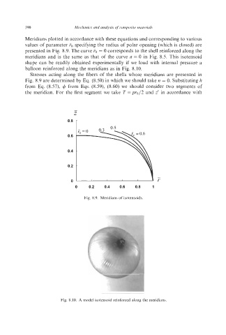
Meridians plotted in accordance with these equations and corresponding to various
values of parameter FO specifying the radius of polar opening (which is closed) are
presented in Fig. 8.9. The curve TO = 0 corresponds to the shell reinforced along the
meridians and is the same as that of the curve n = 0 in Fig. 8.5. This isotensoid
shape can be readily obtained experimentally if we load with internal pressure a
balloon reinforced along the meridians as in Fig. 8.10.
Stresses acting along the fibers of the shells whose meridians are presented in
Fig. 8.9 are determined by Eq. (8.50) in which we should take n = 0. Substituting It
from Eq. (8.57), 4 from Eqs. (8.59), (8.60) we should consider two segments of
the meridian. For the first segment we take T =pro12 and z’ in accordance with
0.6
0.4 -
0.2 -
-
0 r
0 0.2 0.4 0.6 0.8 1
Fig. 8.9. Meridians of isotensoids.
Fig. 8.10. A model isotensoid reinforced along the meridians.